This page describes how to create a 3D model of the fuselage from it's 2D top and side view. Sample images are made for small flying wing I'm building. If you have any comments or suggestions please send me an e-mail.
Arne Ansper <arne@cyber.ee>
I'm using IntelliCAD 2001 from CADopia. Evaluation version is freely downloadable and it's pretty good for 2D jobs. 3D support is not so good and somewhat buggy. Rendering is not available in evaluation version.
For viewing 3D models in DXF format I found really good (and free) viewer: AEC|VIZ reader from AEC VIZ. 3D snapshots in this page are taken from AEC|VIZ.
Scripts are written in Perl. You can get a Perl system for Windows from ActiveState.
Idea is very simple. You position your servos, receiver, battery, etc and draw a side and top view around those components in 2D. Look at the following picture:
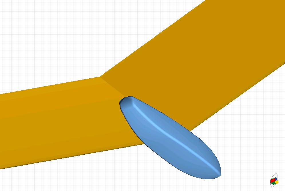
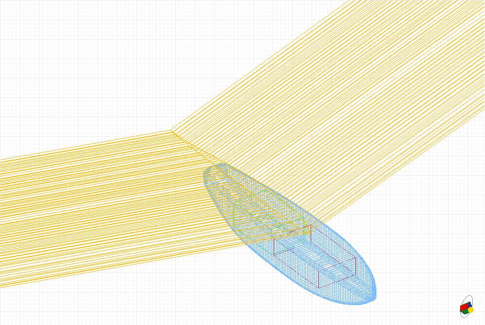
Now you export the four lines: top, bottom, left and right into four files and run a Perl script that will create a 3D model. Script assumes that you will build a balsa box type fuse and round of the edges. You can adjust the radius of the edge. If you make it really big the fuse will look like a molded one, with rounded sides (the orange fuse below). If you set the radius to zero then the fuse will have sharp edges. Additionally you can adjust the number of polygons in 3D mesh.
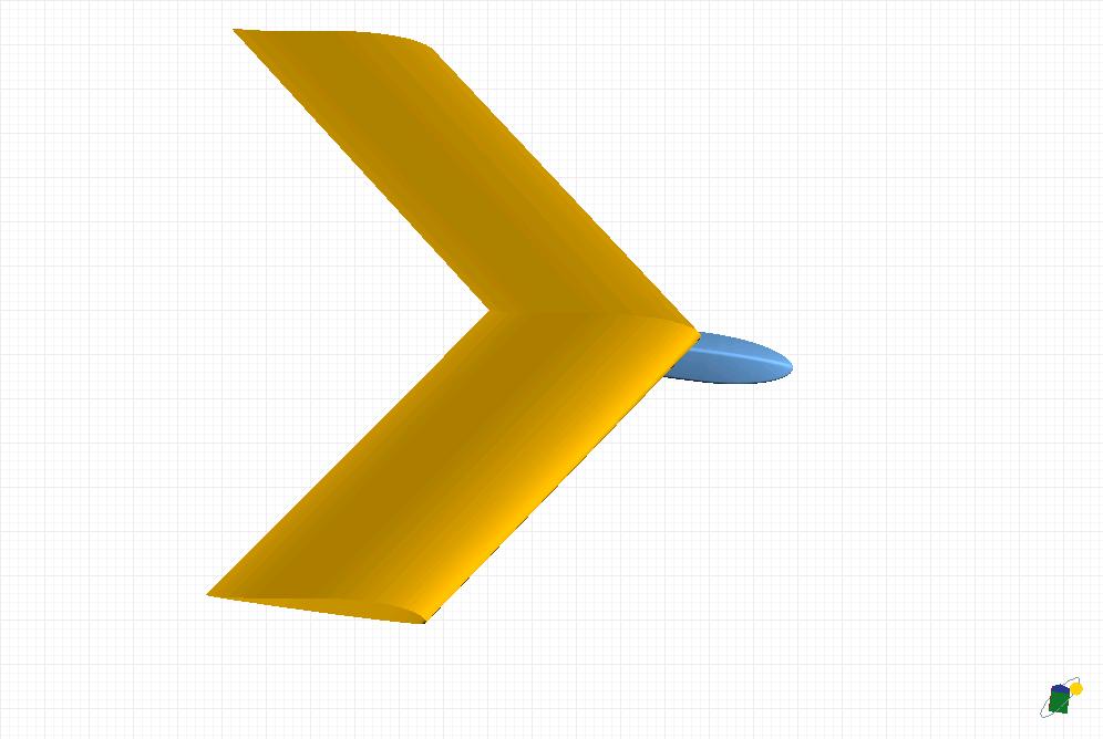
The Perl script creates a script file for IntelliCAD that you can execute using Tools/Run script... command. You can add additional components if you wish: receiver, servos and battery (to see if they fit inside the round-edged fuse), wings (importing a wing profile, copying it to wing center and tip and then creating a ruled surface between those two copies will create a nice wing, see the last pictures), tail feathers, etc. You can assign colors to components in IntelliCAD. Then save the DXF file and open it in AEC|VIZ. Turn on the shading, rotate it and enjoy!
How to export the data from IntelliCAD to Perl script.
First: script only understands straight polylines. No ellipses, no arcs, no splines. What I did: I created suitable outline using ellipses, arcs and straight lines. Then turned on Nearest Snap, zoomed in and created a polyline manually by following the previosly made outline. It's dedious, but it works.
Second: select the polyline and enter command: Tools/Inquiry/List entity info. IntelliCAD prints out polyline coordinates. Right click, select Copy history. Open notepad (or VIM), paste. Remove all other data so that only coordinates of the neede polyline remain. Save the file under appropriate name (the script expects to find four files in it's execution directory named top.src, bottom.src, left.src and right.src).
Third: tune the script. Variables that you can change are: xunits - how many polygons to draw spanwise, arcunits - how many polygons per corner (5 is already really smooth), radius - how rounded are the edges. Run the script. It will create a file boxfuse.scr in current directory. Load it into IntelliCAD.
Below are two fuselages for Libell as seen from various angles. Orange one has completely rounded sides.
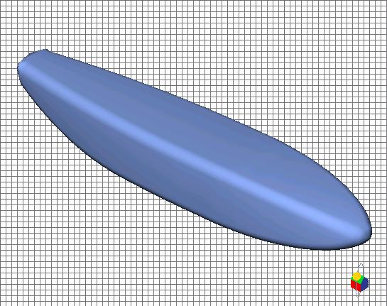
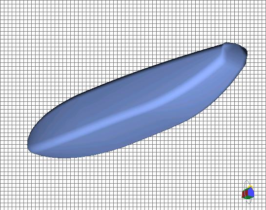
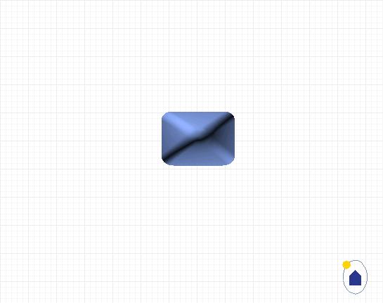
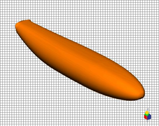
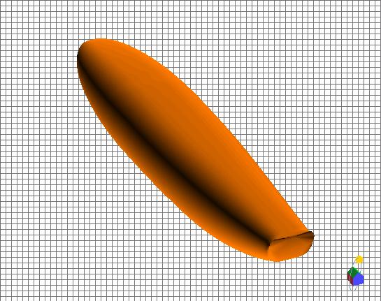
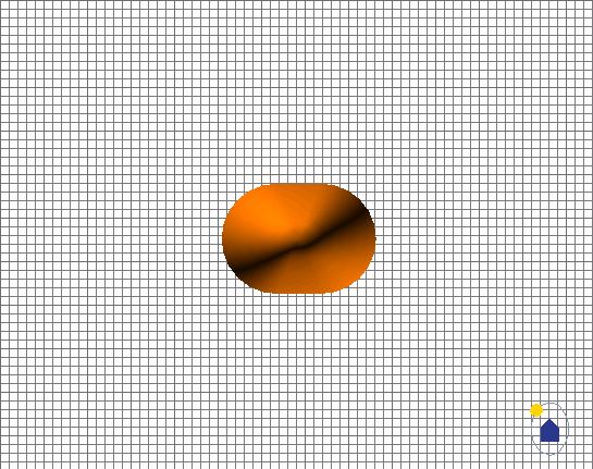
Following images are quite big, so I linked them. Btw, the edge radius is 3mm.