This page describes small flying wing I'm building. If you have any comments or suggestions please send me an e-mail.
Arne Ansper <arne@cyber.ee>
It will be one-piece plane that will fit into my car. This determines the wingspan: no more than 1240mm (~48"). Since I live in flat place, it must fly well in very small slopes in very light lift and even thermal in hot day from handlaunch. I'm not going to fly combat with it and I'm not going to winch or high-start it. It is supposed to be very mobile plane: grab it from car, toss it, fly 20 minutes, put it back and drive away.
My design is based on "Spariane Competition" by Hartmut "Siggi" Siegmann. (Check out his website: http://www.aerodesign.de/, it's fantastic. It's in German and since translator.go.com is out of business and other translators don't translate the whole webpage, it's a little bit hard to read, but it's really worth the effort IMO).
I made following changes to original design:
Details that are not on the plan:
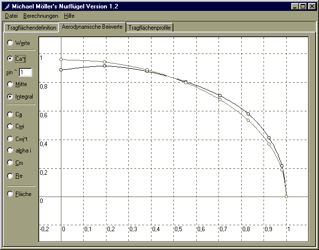
I used Michael Möller's program "Nurflügel" to analyze my wing. You can get this program from Siggi's site. First read the tutorial!
Here is my design: small1.fmd. Additionally, here is the same design in John Hazels liftroll.xls: small1.xls.
Here are the results of the calculations for 5% stability margin:
And here is lift distribution graph, compared to elliptical distribution. It's not perfect, but hopefully not too bad. BTW, with 7% stability margin the lift distribution is perfect, but the Cl is then just 0.3.
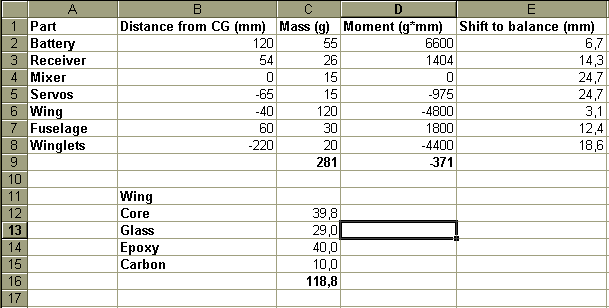
I in order to get some idea how the plane will balance, I created a small worksheet, which calculates the moments of all components around the desired CG, sums them and later calculates how far should I move any component to balance the plane. The most interesting finding for me was the huge importance of light winglets.
Basic construction will be fiberglass over white EPS foam with unidirectional carbon fiber spars on top and bottom. Since I don't plan to use winch or bungee to launch it, I will use the lightest white foam (15kg/m3) and put a single layer of 58g/m2 glass on it (diagonally). The trailing edge is reinforced with unidirectional carbon fiber layed at 45 deg relative to trailing edge at the top and bottom. This makes the elevons torsionally rigid. The leading edge is formed from UD carbon tows. The center of the wing and the servo locations get additional layer of glass.
Initially I planned to glue the wing halves together before covering in order to use a single long piece of carbon running from wingtip to wingtip for spar and cover the whole wing at once. I hoped to make the wing stronger at the center.
However I was afraid that building the wing this way will be be much more complicated and asked some questions about covering swept wings in rec.models.rc.soaring. Mr Robert Steinhaus was very kind and explained to me how to cover the wing this way. He warned that this will be more complicated and suggested that such a small wing does actually not need the additional strength.
So, I have decided to cover the wing halves separately and join them later.
I found a guy who has the CNC hotwire cutter from Step-Four and I can use it to cut my cores. Which means I don't have to make templates :)
Plan I'm planning to cut cores with correct anhedral, so that when I glue the wing beds together I have flat bottomed jig for wing construction. I will also cut the channels for servo leads and antenna with CNC cutter. The channel will be 5mm diameter and located just behind the servo.
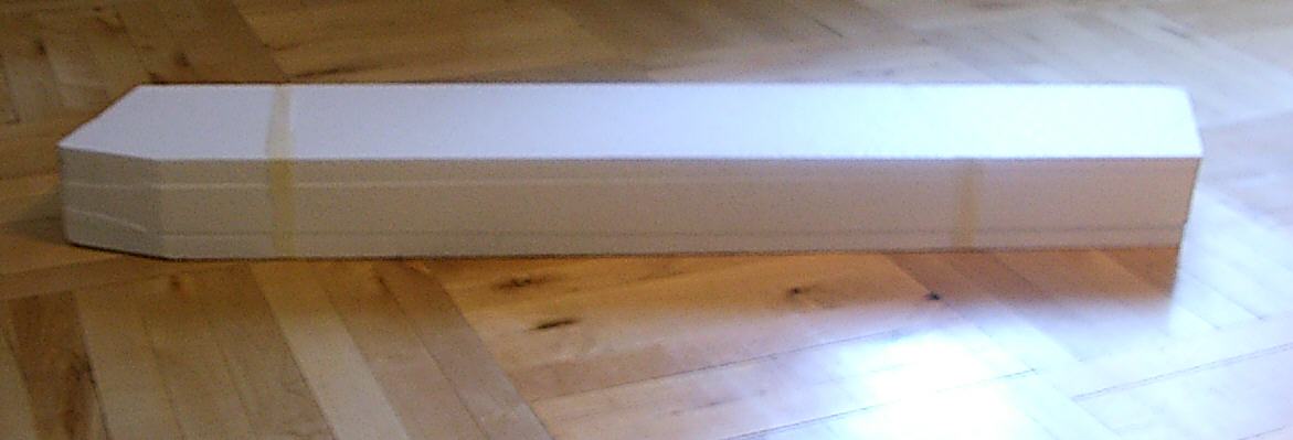
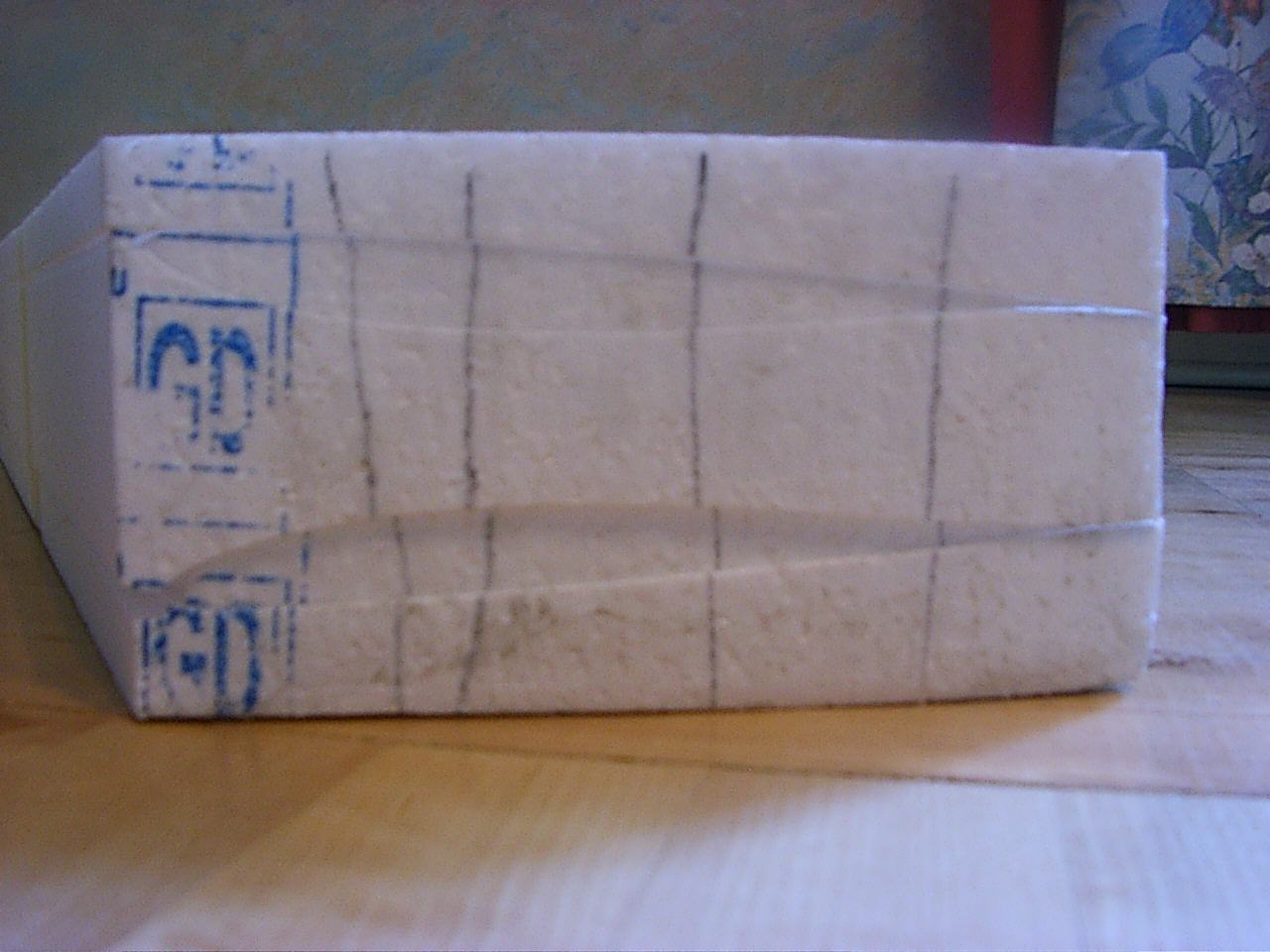
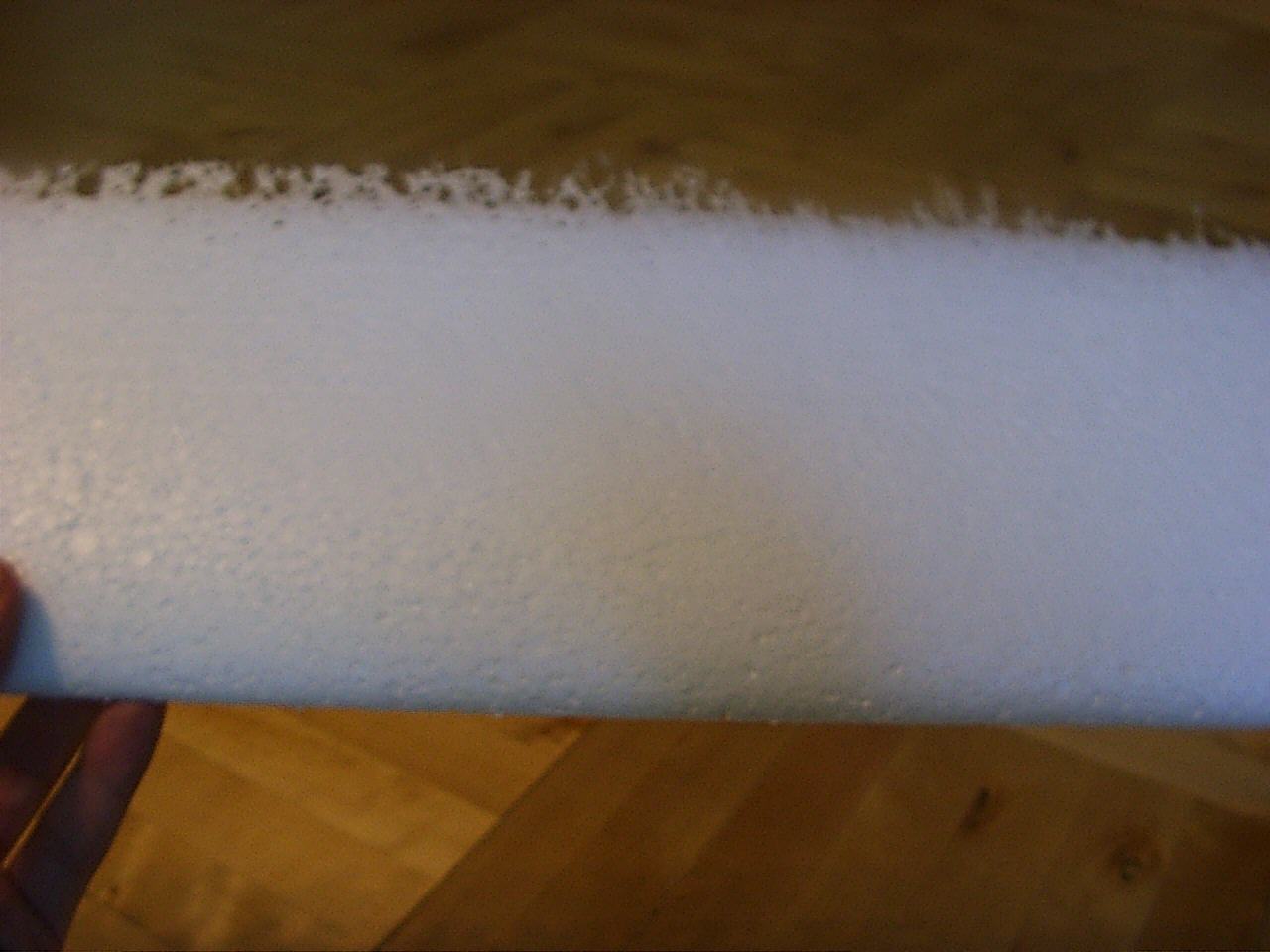
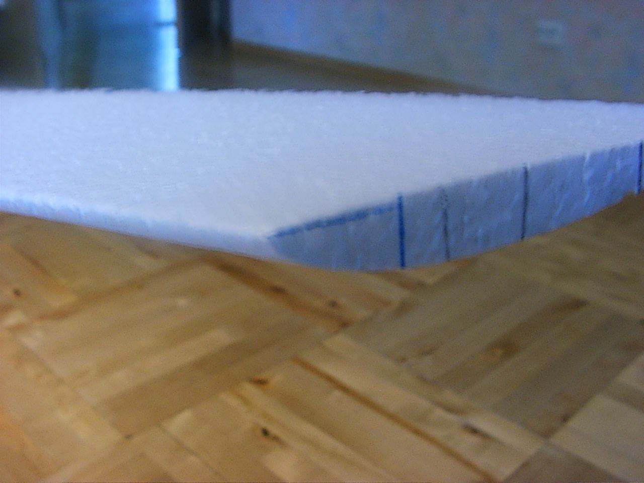
Reality I cut the two cores together from single block of foam. There are three beds: lower, middle and upper. I must cover both winghalves at once. This was probably a mistake :(. I didn't cut the channel for servo leads either. I will melt the channels into core after covering the wing, by sticking the hot metal rod from wing root towards the tip. And the block is oversized: it's 1000mm long instead of 620mm so I must cut one end off.
Pictures of wing: Cores in beds, Tip of the foam block, Trailing edge, Leading edge
The next picture is little bit outdated. Both horns will actually be shorter. I considered using the RDS too, but I was unable to figure out how to setup a differential without computer radio. I'm still thinking that perhaps I should move the pushrods to the bottom of the wing in order to reduce the drag. But then I should add the covers to pushrods in order to protect the servos on landing. I also considered hiding the pushrods into wing, so that they are actually exiting from the wing right in front of trailing edge, but this will make the installation a little bit harder.
One more thing that I'm worried about: since the hingeline is not perpendicular to the pushrod but at 70 deg angle, the control horn will skew relative to the pushrod when the elevon moves (I must add a picture to clarify this). Siggi suggests to use the ball linkage: this allows the pushrod to turn as required, but this construction seems to be so heavy. I would like to use carbon pushord with added Z-bend. Will it cause too much slop when the Z-bend turns left and right in the control horn hole? I've also seen that some people solve this problem by mounting the servo so that the pushrod is perpendicular to the hingeline but not inline with airflow. I think that this will cause too much drag.
I plan to mount the servos from the bottom of the wing. The pushrods will be on the upper side. I will cut the servo holes before covering, fit the servos, fill the holes with the cutouts and cover them with small patch of packing tape, about 5mm wider than cutout from each side. The packing tape will keep the covering from sticking to core. After covering I will cut around this patch from three sides to create a hatch for the servo, remove the foam cutout, install the servo and close the hatch with three stripes of clear packing tape.
I plan to made them from 2mm balsa and either fiberglass them or cover with Tyvek. Fiberglassed winglets look better and since I'm going to mess with epoxy and glass anyway it's not too much more work. Since I've never worked with fiberglass and epoxy before this will be like a training before I start covering the wing.
I plan to attach winglets using small nylon bolts.
I tried to avoid one but finally gave up. Getting the CG right is much more easier and I my receiver is just too big for such a thin wing.
I'm planning to build a balsa-box type fuselage and fiberglass it. The fuselage is attached to the wing using two nylon bolts. There are no hatches in the fuselage. Radio equipment is installed from the top before I attach the fuselage to the wing.
Check out the 3D views of the fuse and the tools used to create them.
I have Hitec Focus 4AM radio. This is a non-computer radio without mixing function that is required for elevons. I built several mixers for it.
I bought two Simprop SES170BB servos for elevons. They a quite new design, very small (22mm, 19mm, 11mm), weigth only 9 grams, give 1.7 N*m (that is about 15oz-in according to my calcuations) torque at 6V and I got 10% discount on local hobby shop for them :)

I checked my servo setup using Craig Tenney's excellent worksheet and found that the servos are powerful enough. According to the calculations I need 4 oz-in of torque when flying with 20 degree deflected elevons at speed 128km/h (80mph). Since I'm not going to fly combat with it, the absence of metal gears is not a big tragedy :)
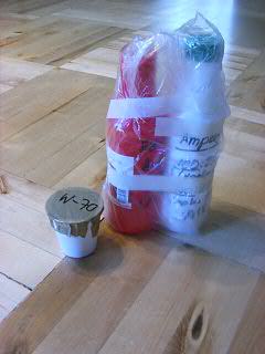
It's really hard to find suitable materials in Estonia :( Mail-ordering is possible but the shipping costs will be enormous when buying such a small amount of epoxy or glass. Fortunately mr. Heino Kőrvel from Tragi Ltd was very kind, gave me a lot of good advice and finally sold me all the required materials.
Wax and resin (in ketchup bottles)
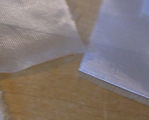
Fiberglass On the left is a Russian glass (27g/m2) that I will use for winglets and fuselage, on the right is a German glass (58g/m2) that I will use for wings.